
How it's built
Daily Five.
Five switches, five icons. This is how it comes together.
-
01 What you need
- 3 printed parts + 5 projectors (white)
- 5 × toggle switch, SPDT
- 5 × RGB LED 5 mm, common anode
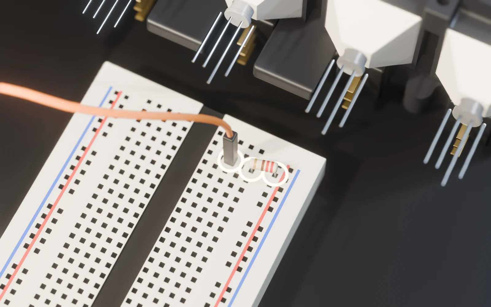
- 5 × 220 Ω
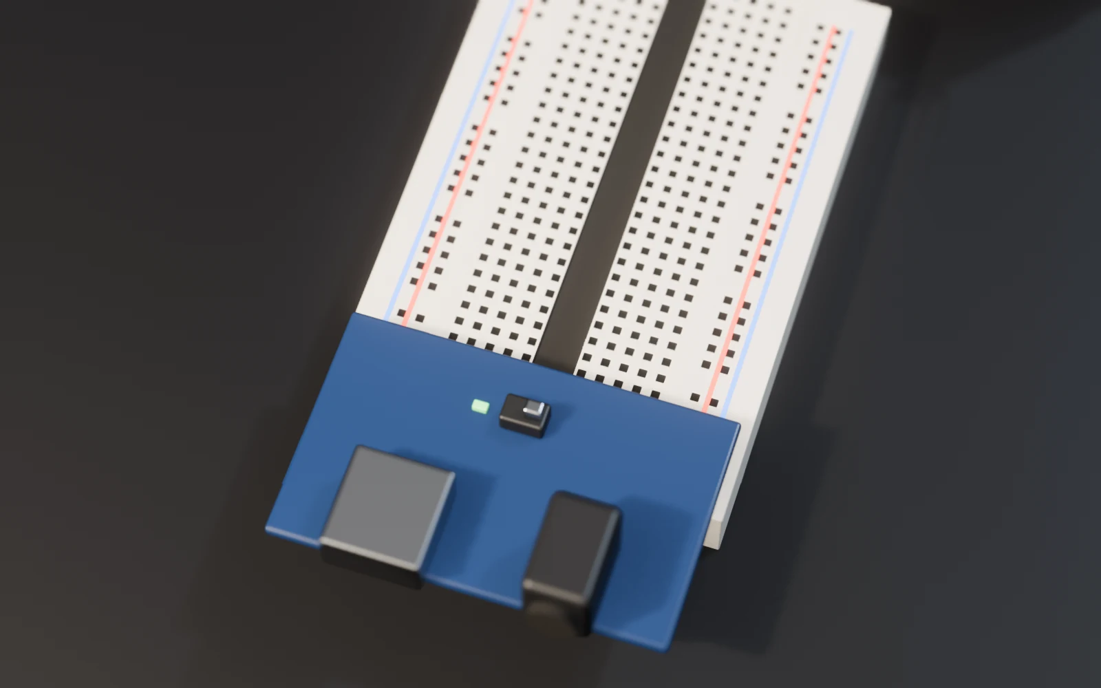
- MB102 power module
- 400-point breadboard
- Jumper wires
- 4 × M3 × 6
-
02 Print
Your 3MF from the builder, no supports. Print the projectors in white.
-
03 Switches
-
04 LEDs
The long leg is the anode.
-
05 Wiring
- 5 V → 220 Ω → long leg
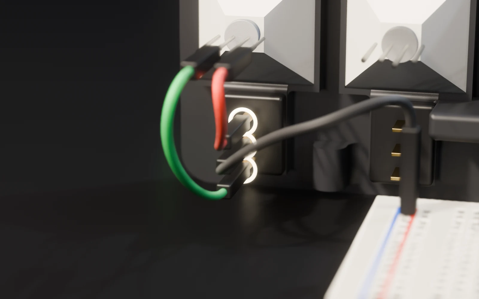
- GND → middle pin
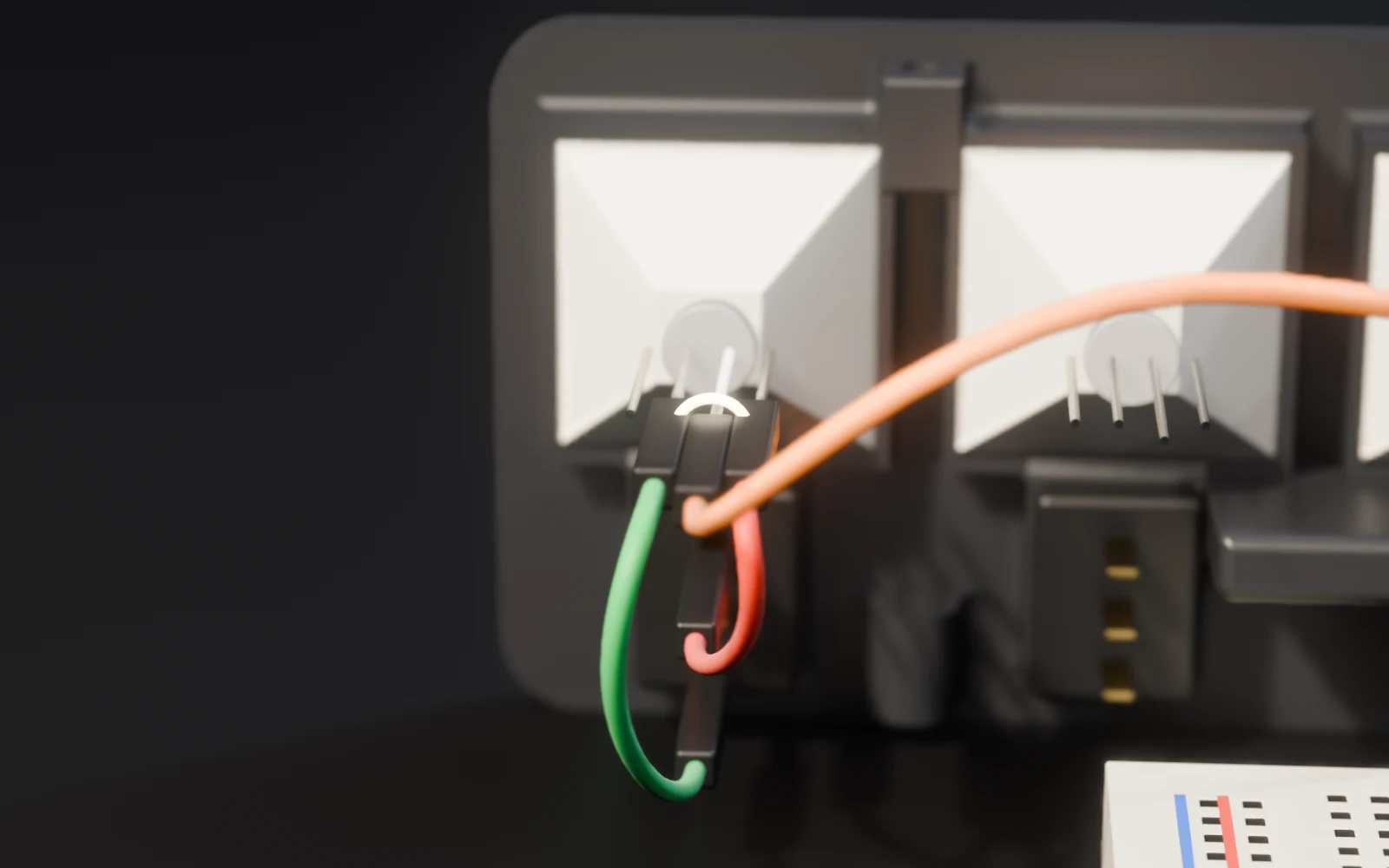
- top pin → red
- bottom pin → green
-
5.1 …
…
-
5.2 …
…
-
5.3 …
…
-
5.4 …
…
-
5.5 …
…
-
5.6 …
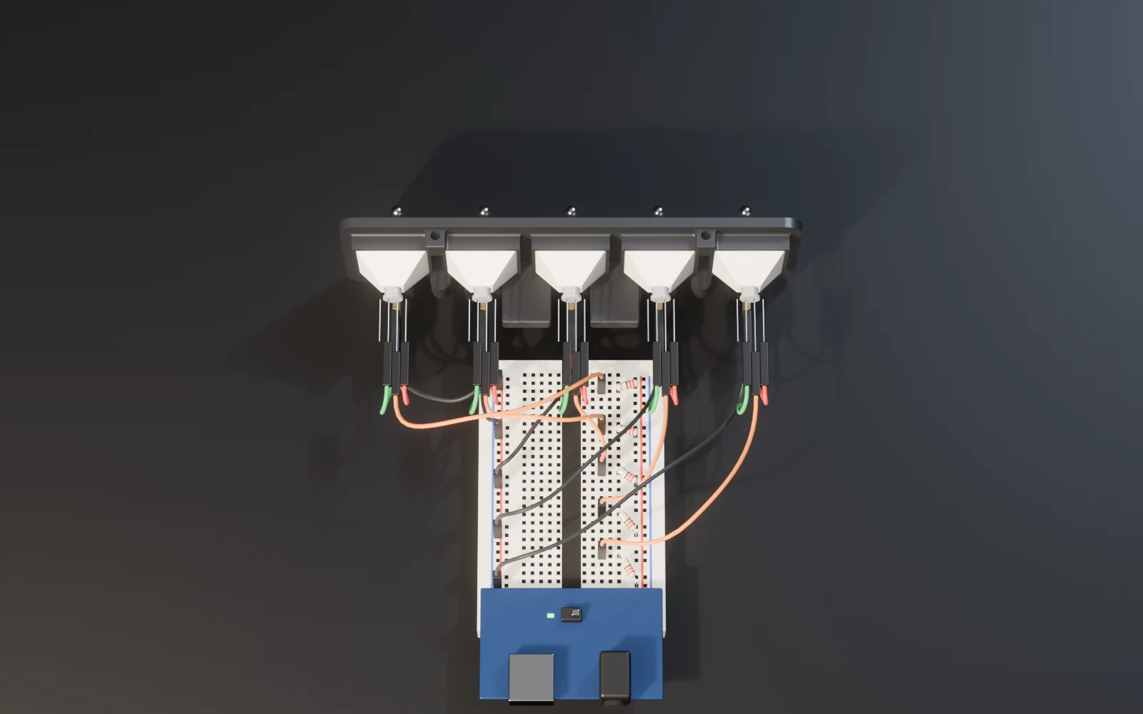
…
-
06 Close it
Board first, then the panel. Four M3 × 6.
-
07 Done
Red is pending. Flip it: done.